
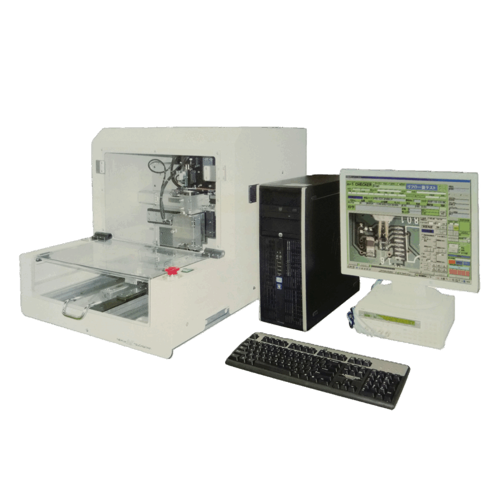
First Article Inspection / Verification System for PCB
Electrically and Optically Verify Identified SMD in PCB (Printed Circuit Board)
Assemblies Before Mass production
- Rapidly and Accurately Verify Identified Mounting Errors of PCB in the 1st Product of New Assembly Production or Changeover for Prototype or Pre-Production.
- Eliminate Human Errors Related Faults and Reduce Time Consumption to Rework for Developing to Provide Highly Productivity and Cost-Effectively.
- Automate Providing Traceability Electric Test Data Reporting and Data Management for Internal and Customers Use as Reference Data of Quality Assurance.
Functions
- Automate Measuring SMD (Chip Capacitors and Chip Resistors) by an LCR Meter, and then Verifying and Judging Inspection / Verification.
- Support Human Optical Inspection / Verification Mode that Allows Mounting SMD Status to Inspect and Verify (Type of Component, Component Format, Descriptions Dimensions Orientation, Polarity, and Printed Alphanumeric Characters) on the Display Monitor.
- Automate Generating Test Program with the Mounting Data and Component Parts List (Parts Library).
特長
Automate Impedance Measurement System
Accurately automate measuring CR (Capacitance and Resistance) using probes by an LCR meter, and enables the
n=1 Checker to automate verifying and judging the measurement results compared with the Parts Library as well as
automated save all data into the database. All data can be used for both internal and customers’ quality assurance.
Human Optical Inspection / Verification System
Supporting a CCD camera that automates verifying the identified mounting status of each component on the display monitor
of the n=1 Checker, and enables it to visually inspect showing optical inspection results compared with the Parts Library(e.g.,
type of description in printed alphanumeric characters, orientation, dimension, polarity, and Pin #1 identification).
Test Program Generator (TPG)
TPG is a program that automates generating test program from mounting data and component Parts List (Parts Library)
for the n=1 Checker.
Other Software Features
The software is designed for user convenience and ensures work efficiency.
Functions for component height search and workpiece offset acquisition are built in.
The software is designed for user convenience and ensures work efficiency.
Functions for component height search and workpiece offset acquisition are built in.
Specifications
| M size | L size | ||
| Basic Specifications | Net Weight | 92kg | 118kg |
| Dimensions | W660 x D805 x H625 mm ( Approx. W:2.17 x D:2.64 x H:2.05 ft ) | W860 x D975 x H640 mm ( Approx. W:2.82 x D:3.20 x H:2.10 ft ) | |
| Test Area | X:330 mm (13.0” ) Y:250 mm (9.8” ) | X:510 mm (20.0” ) Y:380 mm (15.0” ) | |
|---|---|---|---|
| Test Duration | 2 Second per Component ( Typically ) | ||
| of Measurement Steps | Max. 10,000 Steps | ||
| Impedance Measurement | Component Test | 2-terminal chip capacitors, 2-terminal chip resistors, chip-type module resistors | |
| Component Size | 0402、0603、1005、1608、2125、3216(3225)、4532、5025 | ||
| Component Mounting Angle | 0、90、180、270 deg 【45 degrees or Free Angle degrees optional】 | ||
| Measurement Range | C、0.94pF-199.99mFR、0.01Ω-199.99MΩ(on independent C and R scales) | ||
| Measurement Voltage | 1Vp-p、50mVp-p | ||
| Human Optical Inspection / Verification Support | Component Display Area | 6 x 4 mm (461 dots horizontally x 307 dots vertically) | |
| Collation Display Area | Component size, mounting angle, printed alphanumeric characters for type descriptions, 1-pin direction, positive orientation, cathode orientation, missing component | ||
*ALL SPECIFICATIONS AND DATA FOR THE n=1 Checker ARE SUBJECT TO CHANGE, MODIFY, OR OTHERWISE FOR IMPROVING THE PRODUCT QUALITY WITHOUT NOTICE.